Michael Droettboom wrote:
Ahh -- 0.91 avoided this by using non-antialiased rendering by default for pcolor as well as pcolormesh. That's probably what Rob is seeing when he went from 0.91 to 0.98.
I suspected that.
Of course, non-antialiased rendering has its own quality limitations, and it only applies to the bitmap backends. The moire pattern still appears in (for example) a pdf viewed with Acrobat Reader without the edge workaround.
True. Still, it might be that turning off antialiasing is part of the best compromise for some backends. We weren't getting complaints with 0.91, as far as I recall. There may be speed considerations here also.
Eric -- maybe we should experiment with different values for the edge width to find a good compromise. Also, it might be good to add a
Yes, this is worth some more experimentation. A problem is that the edge width is specified in points, and the effect of this will depend on backend and scaling. If it turns out that there is an optimal value for each backend then we could pass in a special value for this case, say -1, which would be intercepted by the backend and converted to whatever works for that backend.
As you note, the problem is made even more complex by the fact that different programs may render the vector graphics (pdf, ps, svg) differently.
Someone must have already sorted all this out for some software project, somewhere. Does cairo handle it better? I have not looked yet.
regression test example where the edge workaround introduces noticeable negative artifacts. quadmesh_demo.py (with its built-in smoothness) doesn't really highlight the problems with that approach.
Yes, a really good set of test cases would help.
Eric
···
Cheers,
Mike
Michael Droettboom wrote:
Ok -- sorry about that. It looked pretty good on the quadmesh_demo example, but I suppose that's just by accident due to the nature of the data. By this assessment, we should probably back out this hack in pcolormesh as well.
Curiously, though, Rob says this is new behavior...
Cheers,
Mike
Eric Firing wrote:
Michael Droettboom wrote:
Rob Hetland wrote:
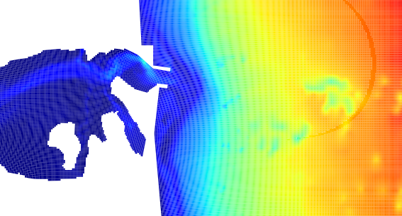
When I do a pcolor, there are white lines between the patches that cause strange moray patterns, even when saved to a png. The attached sample shows what I mean. Notice the strange coffee-cup ring, where the pattern goes away. This is new behavior. Unfortunately, I haven't been paying enough attention to the devel list to know what the changes that cause this might be.
The quads need to be enlarged by about 1 pixel, and the easiest way to do this is to give them an edge of width 1 pixel. The pcolormesh code has had this fix for a while, but it was overlooked for pcolor. (Both of which were virtually rewritten for 0.98, which is why this is a regression from 0.91).
I have fixed this in SVN.
Mike,
Not exactly. This is a very old problem and an old attempted solution. I struggled with it a long time ago, and among the various combinations of backends and antialiasing settings, I never found a completely satisfactory solution. I don't know what the best solution will be, but a linewidth of 1 point is definitely not it. It is fundamentally wrong--expanding the patch dimensions by 1/144 inch, so that they overlap--and consequently creates its own artifacts. If you run the attached script and look at the ps output, you will see artifacts in the rectangle corners, and some of the tick marks will be more misplaced than they used to be relative to the rectangle boundaries.
I'm sorry I don't have a good solution right now and can't look at it in detail immediately, and I don't mean to dump more work on you. Let's just consider the issue as open for discussion and investigation. I can try to get back to it later.
(It is conceivable that a thinner linewidth will be an adequate compromise--still a hack, but maybe acceptable--although the last time I worked on this problem, long before 0.98, I could not get it to work well under all circumstances.)
Eric